Step 4 - Review the staged model sequence
Next, you need to review the staged models. Go to the Tooth Movements tab and verify that the series is feasible and meets your treatment objectives.
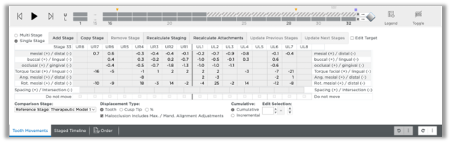
The stages are automatically numbered 1, 2, 3, etc. and are listed across the top left as small tabs within the Tooth Movements tab. When this area first appears, the tooth movement values are displayed as cumulative amounts and the last stage is selected. It contains the total tooth movements. You have many options for viewing tooth movements to ensure that the values are appropriate.
Stages that have an asterisk indicate that manual changes were made in that stage.
Cells highlighted indicate the following:
- If you removed stages and/or modified any of the movements, any values that exceed your constraints are highlighted in yellow.
- As the teeth move linearly to the next stage, interferences can occur. Values that represent an interference are highlighted in orange in the Spacing (+) / Intersection (-) tab. You can resolve these interferences by:
- Adjusting movements in the previous or next stages
- Adding stages as needed

The Staged Timeline tab shows the starting and ending stages for each group of movements. The system shows the maximum actual movement per stage in each cell.
You can also view the movements by tooth. Switch between upper and lower arch at the top left of the Staged Timeline tab.
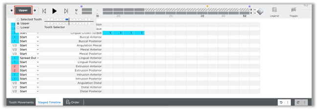
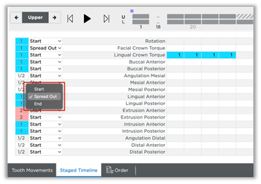
You can change the starting (first stage) or ending point (last stage) for each set of movements by choosing Start or End or choose Spread Out to spread the movements throughout the stages. Start and ending stages for a movement type can extend over multiple groups.
Choose a Displacement Type

- Tooth - Click the Tooth option to see tooth movements calculated from the center of each crown.
- Cusp Tip - Choose the Cusp Tip option to see tooth movements calculated relative to the cusp.
- % - Choose this option to see tooth movements calculated as a percentage of movement, with the target represented as 100%.
Choose whether to view values cumulatively or incrementally:
- Cumulative – The tooth movements of each stage are added together to show the total movement planned through the current stage.
- Incremental – The tooth movements of each stage show the amount of movement planned between the previous stage and the current stage.

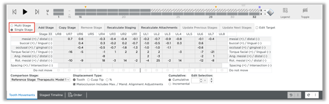
Check model movements in Single Stage view:
- Select the Tooth Movements tab then select the upper or lower arch.
- Display and view the 3D model as needed so that you can watch the model as it changes from stage to stage.
- Select the Single Stage view. Click the model numbers in the small tabs (or use the animation player discussed in the next section). The tooth movements are shown for each model in the series.
- Examine the tooth movement values. If needed, adjust the numbers using the table.
- Repeat for the opposing arch.
Animation player:
Use the animation player to view the movements in the staged model sequence. It is available on both the Tooth Movements tab and the Staged Timeline tab. The animation player runs an animation of the entire treatment plan, showing tooth movement from the initial state to the final tooth position.
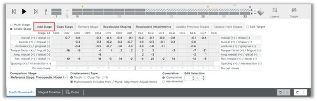
Add stages as needed:
- Select the upper or lower arch.
- Select a model number to follow the new stage you are adding.
- Click the Add Stage button to insert a new stage. The tooth movements for the new stage are set to a midpoint between the preceding stage and the following (new) stage.
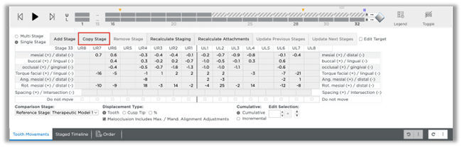
Copy stages as needed:
- Select the upper or lower arch and select a model number.
- Click the Copy Stage button. A new copy of the selected stage is created following that stage.
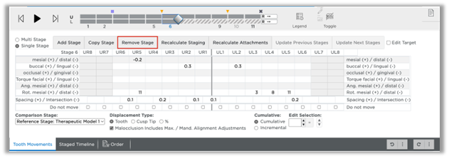
Remove stages as needed:
- Select the upper or lower arch and select a model number.
- Click the Remove Stage button. The incremental movements for the subsequent stage are recalculated to include the movements that took place in the removed stage.
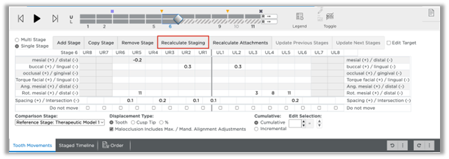
Recalculate staging as needed:
- Select the upper or lower arch and select a model number.
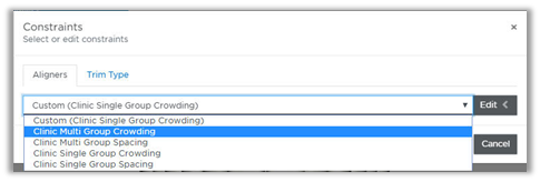
- Click the Recalculate Staging button. The Constraints dialog box opens. You can change the constraints setting from the drop-down menu and/or click Edit to modify the groups and/or maximum rates of movement for this patient.
Recalculate attachments as needed:
- Select the upper or lower arch and select a model number.
- Click the Recalculate Attachments button.
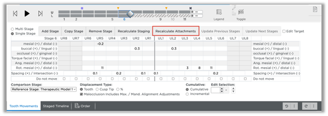
The Constraints dialog box opens. You can change the constraints setting from the drop-down menu and/or click Edit to modify the automatic attachment placement for this patient.
Update Previous Stages as needed:
- Select the upper or lower arch and select a model number.
- Click the Update Previous Stages button.
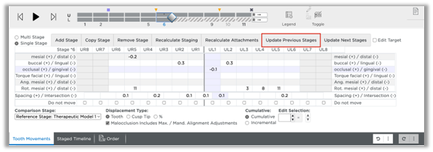
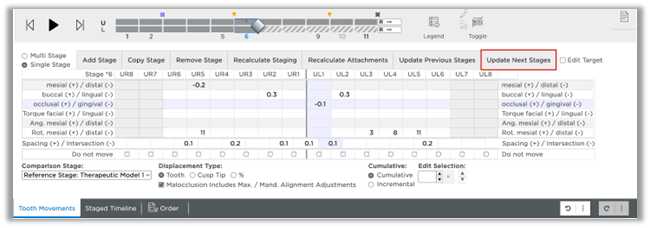
Update Next Stages as needed:
- Select the upper or lower arch and select a model number.
- Click the Update Next Stages button.

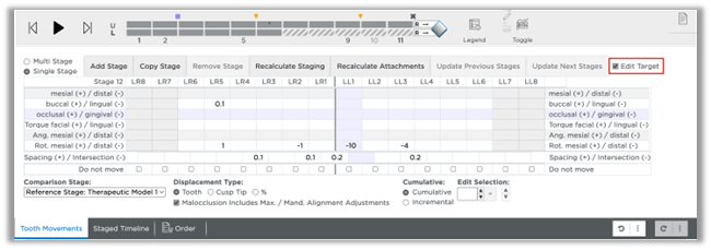
Edit Target:
Click the Edit Target check box to edit the target, passive and retainer stages as needed.
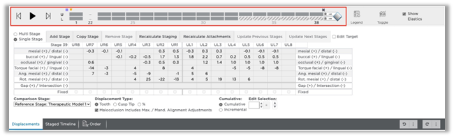
Re-check movement with multi-stage view
Now examine the movements per tooth through the stages:
- Select the Multi Stage view.
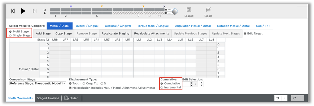
- Select the upper or lower arch.
- Select the tabs as needed to view types of movements (Mesial/Distal, etc.).
- Repeat these steps for the opposing arch.
Adjust Tooth Movements manually
- Select the upper or lower arch.
- Select the Cumulative or Incremental option as needed.
- Enter new values according to your clinical judgment.
- If you have manually changed values that affect previous or later stages, click the Update Previous Stages or Update Next Stages buttons to adjust the numbers.
Check IPR
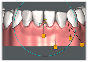
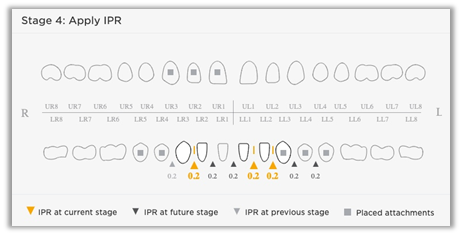
SureSmile® automatically inserts an indicator (orange triangle) to show when to apply IPR.

IPR is indicated on the 3D model with a small gold label with a number indicating the amount of IPR proposed by the system.
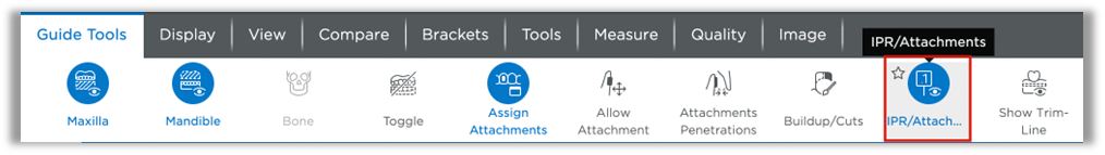
To turn these labels on/off go to Guide Tools and click the IPR/Attachments icon.
The IPR indicators are shown on the timeline and on the 3D model. Hover over the gold inverted triangle on the timeline with your mouse to display this IPR pop-up for the stage shown in the 3D window.
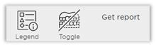
The Get report button appears on the timeline after you approve the staged models.
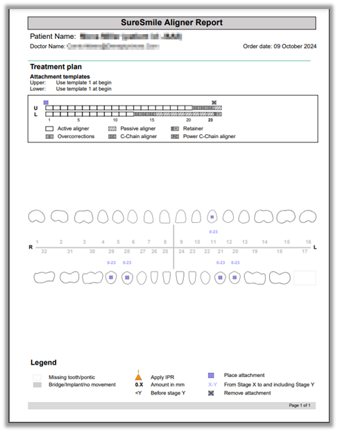
The Aligner report shows the timing and placement of IPR. It also shows when to add and remove attachments. It is only available for Aligner orders; it is not available for 3D prints or STL exports.
Print the report and refer to it chairside during the patient appointment.
Note: You can also access this report on the Patient Overview. Click Reports and select it from the list.
Over-correction
Over-correction can be applied to the staged model sequence. You can specify in your Preferences how many Over-correction stages to apply as well as thresholds for particular movements.
Click the settings icon ![]() , then click Preferences.
, then click Preferences.
Click the Aligner Overcorrections tab. Next to Over-Correction Type choose Amount or Percent. Use the check boxes under Include Over to include or exclude particular movements. Change the movement thresholds under Threshold as needed. Change over-correction values under Over Amount or Over % (depending on which over-correction type you chose). Choose how many over-correction stages to apply next to Apply Stage Count Maximum. Click Save.
Over-correction stages
If you asked for overcorrection in your setup prescription, the Digital Lab will apply stages of overcorrection at the end of your staged model sequence. Overcorrection stages are indicated with the letter “O”.

The Overcompensation Stages icon found in the Display palette can be used to hide/show the over-correction stages.

C-Chain & Power C-Chain
If you asked for C-Chain or Power C-Chain in your prescription, the Digital Lab will apply 3 consecutive stages at the end of your staging. C-Chain and Power C-Chain stages are indicates respectively as “C-C” and “P-C”